Episode 6: Plotting Several Pixels

Great, we can switch to a graphics mode and even draw a colored pixel on the screen! But we've drawn at (0,0), the top-left corner – the easiest possible location. How do we draw at other locations?
You'd expect the video memory to be organized linearly, left-to-right, top-to-bottom, in which case the byte offset of any (X,Y) location could be found by
offset = (Y * screenWidth + X) / 2That is:
- Multiply the row (Y) by the screen width -- row 0 starts at offset 0, row 1 starts at offset 360, row 2 starts at offset 720, etc.
- Add the column (X) to move us over to the right position
- Divide the whole thing by 2 since in 16-color mode each byte encodes 2 adjacent pixels.
It turns out that video memory can be stored in a number of different banks, each encoding a different group of scanlines. According to the IBM PCjr Technical Reference Manual pg 2-60, most modes encode even scanlines into a bank starting at 0xb8000 and odd scanlines into another bank starting at 0xba000. This was to support interlaced TVs where a frame is composed by drawing the odd-numbered and even-numbered scanlines in two separate passes. Clearly our calculation must take into account whether Y is even or odd.
But it gets worse... the CGA Plus mode we're using, 320x200x16, actually encodes its scanlines in 4 separate banks:
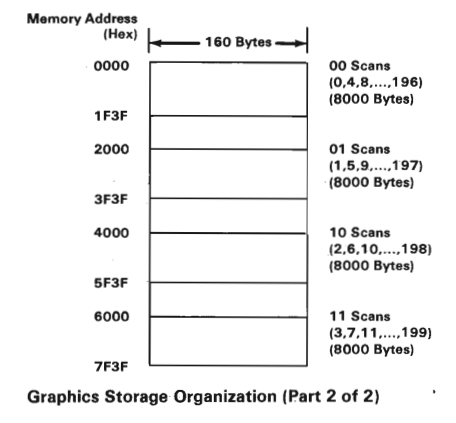
So (counting from 0) scanlines 0, 4, 8, ... 196 are all packed together at 0xb8000, scanlines 1, 5, 9, ... 197 are packed together at 0xba000, and so on. It seems clear that we should divide scanline by 4 – the result will give us the actual row number within the bank, and the remainder will give us the bank number. As an example, 17/4 = 4r1 which tells us scanline 17 is actually the fourth row in the second bank (remainder of 0 would be the first bank). We can multiply the remainder by the bank width, 8000 bytes (0x2000), to get the byte offset where the bank starts. So our calculation in assembler pseudocode looks like this:
  push dx         ; We'll be using DX; push our color for now
  mov cx, 4
  xor dx, dx
  div cx          ; DX <= bank number (0-3), AX <= row within bank
  xchg ax, dx     ; AX <= bank number (0-3), DX <= row within bank
  mov cx, 0200h   ; bank width
  mul cx          ; AX <= bank memory offset
  add ax, 0b800h  ; offset by start of video memory
  mov es, ax      ; ES <= absolute start-of-bank address

  mov ax, dx
  ; Now BX is the pixel column (x) and AX is the row (y) within the bank

  ; Calc byte index of pixel: AX <= (AX * 320 + BX) / 2
  mov cx, 320
  mul cx
  add ax, bx
  shr ax, 1

  mov si, ax      ; Put byte index in string-source register
This presumes AX contains the scanline row, the Y part of our (X,Y) pair. We figure out which bank the scanline is in, calculate the absolute start address for that bank, and store it in ES. Then we calculate the byte offset within that bank using the real scanline number (divided by 4) and the X coordinate, dividing the result by 2 (via a right-shift) because each byte encodes 2 pixels. This value we put into SI.
Now we're all set to address the proper pixel using [ES:SI]. But there's one more problem: Since each byte encodes two pixels, we have to figure out which 'nibble' of the byte corresponds to our pixel. Even-numbered pixels are in the high nibble (upper 4 bytes) of each byte and odd-numbered pixels are in the low nibble. Since SHR sets the carry flag to the bit that was shifted out, we should be able to jump, based on that flag, to a code label that sets the proper nibble. That's what I've done here:
  mov al, [es:si]   ; Pull the pixel pair out into AL

  pop dx            ; Get our color back in DX
  jc .setLow        ; If AX was odd, carry bit should be set from the right-shift. If so, set the low
                    ; nibble, otherwise set the high nibble
  .setHigh:
    and al, 00fh    ; Clear the high nibble
    mov cl, 4
    shl dl, cl
    or al, dl       ; Set it from the color index in DL
    jmp .finish

  .setLow:
    and al, 0f0h    ; Clear the low nibble
    or al, dl       ; Set it from the color index in DL

  .finish:
    mov [es:si], al  ; Push the updated pixel pair back into memory
    ret
For the low nibble, we clear it and preserve the high nibble by masking with 0xf0, then OR in the color palette index from DL. For the high nibble, we do the opposite -- but we have the added step of shifting DL to the left by 4 bits so it can be OR'ed into the proper place. Now let's try out our putpixel function. It will expect the X coordinate in BX, the Y coordinate in BY, and the color index in DL. To streamline the call I made a NASM macro:
; Sets the color of a pixel at an X,Y location.
 ; Clobbers ax, bx, dl.
; %1: X
; %2: Y
; %3: color (1-byte palette index)
%macro setpixel 3
  mov bx, %1
  mov ax, %2
  mov dl, %3
  call putpixel
 %endmacro
Now we can try out out by setting the four corner pixels to light blue, light green, light cyan and light red:
setpixel 0, 0, 9
setpixel 319, 0, 10
setpixel 319, 199, 11
setpixel 0, 199, 12
And the result:
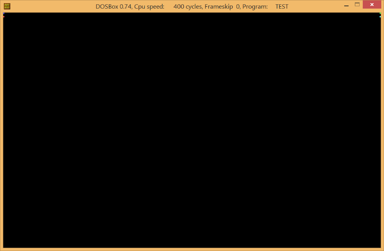
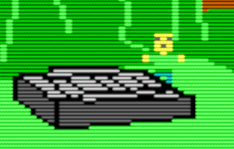
Huh? The bottom pixels aren't in the corners!
I did a little experimentation, changing the pixel Y values, and found out that no matter what values I use, the bottom pixels always go into the first 4 scanlines (corresponding to the first scanline of each of the 4 banks). Sounds like the result of our multiplication is getting clobbered.
Remember that dividing the Y value by 4 (line 4) gives us a result (the row number within the bank) and the remainder (the bank number). The result goes into AX, then we perform an xchg to swap it to DX so we can do some math with the remainder. But our next step is a multiply, the result of which could be a 32-bit number so it has to span DX:AX. Since the result will be at most 0x600 (0x200 * 3), DX will always be 0, so when we go to calculate the actual byte address we've got 0 for the row. A quick fix is to push DX before our multiply on line 7, then pop it just afterward. Let's try it again:
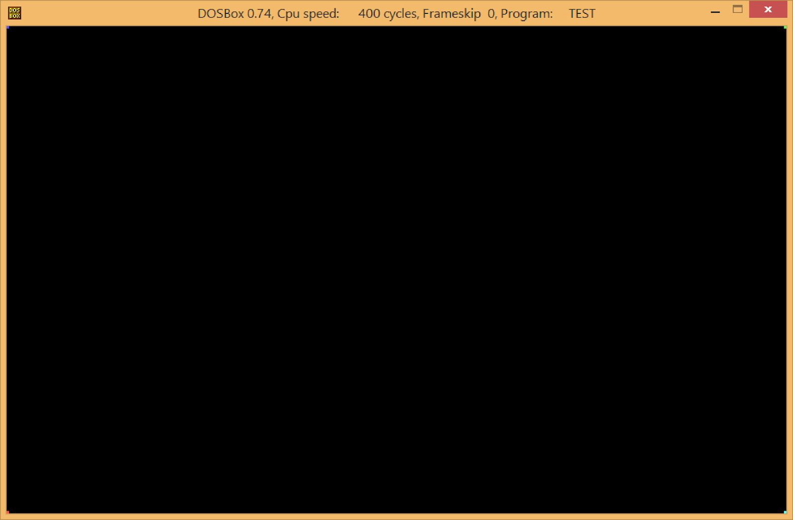
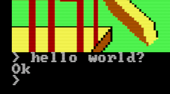
Beautiful!
Lessons learned:
- Remember MUL and DIV work on DX:AX in combination, so
- Before a DIV, make sure DX is the upper-half of the number you want to divide (either sign-extend AX with CWD or clear it DX with XOR DX, DX).
- Before a MUL, PUSH or otherwise store DX if you have something important in it.
- If your program isn't ending, or is ending prematurely, check the following:
- PUSHes and POPs line up
- All procedures have a clear return path; i.e. every possible branch in a procedure will eventually get you to a RET.
As I practice, I'm learning better ways to organize my assembly, so I made a couple more edits that have nothing to do with the code above:
- Removed all the print statements. We just want to see the graphics for now!
- Moved the macro includes to the very top of the file, and put the .data and .bss sections right after them. It feels more organized having variables at the top.
- Read that ASM procedures should return any result in AX as a convention; so int_to_string now returns the DI pointer (which now holds the formatted integer) in AX.
Completed source code for this episode is at:
https://github.com/josh2112/pcjr-asm-game/tree/episode-6